
Many thanks to Mick Nelmes for the “My Ardic Boat Heater” guidance on operation and servicing. A 34 page Service Manual can be found in the Members-only “Documents” area. I found this useful when I had to clean the burner chamber which was heavily fouled with carbon deposits and causing a lot of soot deposits on the boat around the exhaust. Servicing should be carried out by authorised competent personnel and in accordance with appropriate regulations and manufacturer’s instructions.
Have you fitted a Carbon Monoxide Alarm? When did you last test it?
My Ardic Boat Heater Mick Nelmes
Description
 T
T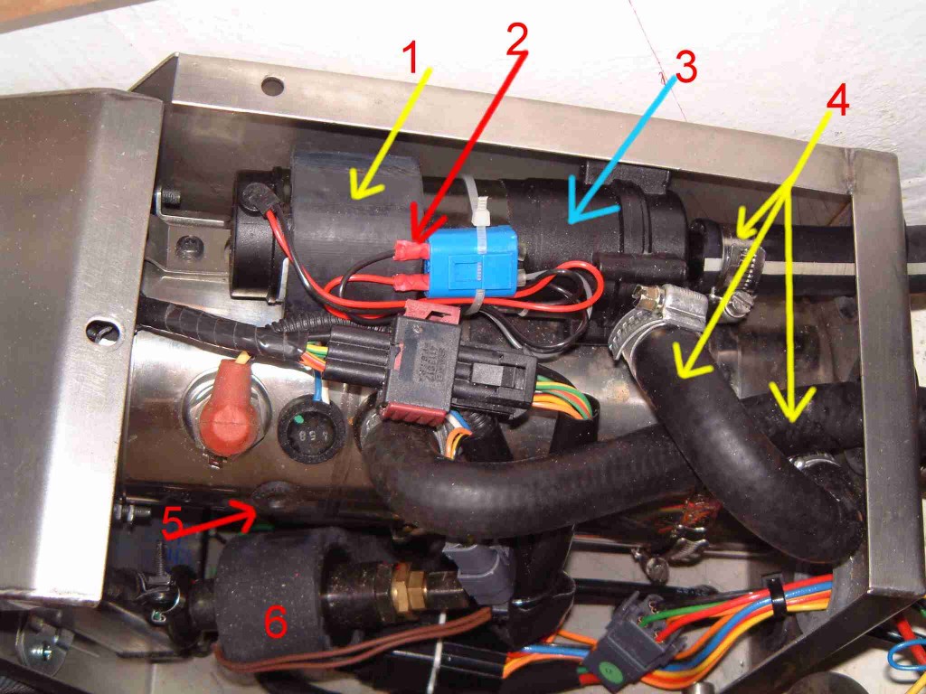 he Ardic heating system consists of a diesel-heating unit and a hot-air unit. The diesel-heater heats water that is pumped into the heating circuit when required. When the engine is running, this heating circuit distributes hot-water from the engine to the hot-water tank heating element and the boat-heater hot-air unit.
This system allows the engine or the boat heater to heat the the hot-water tank and the boat.
Key to photos:
1 Rubber retaining collar for Water pump
2 Bullet connector fitted in original pump connector
3 Water pump
4 Water hoses (left to right – pump inlet, pump outlet/heater inlet, heater outlet
5 Rubber grommet –
remove for access to reset switch (reset switch is to right of hole)
6 Diesel pump
Since the instructions for operation are a bit confused the following may help.
Controls
There are two controls in the boat:
1/ The hot air fan-speed Knob and on-off switch situated on the instrument panel.
2/ A control unit with hot-water heating on-off switch, boat heating on-off switch and boat-heater thermostat.
Operation
Boat heating under engine / no diesel heater
The Fan-speed knob on the main control panel works independently to the heating control. Turning the fan on when the engine is running causes hot air to be pumped round the boat without the diesel heater powered up. The Control unit has no function.
Hot-water via the Heater
Switch ON the top-left switch on the control panel.
Hot-air via the heater
Switch ON both the top-left and the top-right switch on the control panel. Use the thermostat to control boat heating and the Fan-speed switch to control air flow. The thermostat controls the boat temperature.
Problems
Diesel heating unit stops working.
Please only do the following operations if you are confident and competent.
Check that the control unit switches are on, thermostat is turned up and indicator lights are lit.
No lights:
Check the re-settable fuse under the companion way.
In cockpit locker. Lift floor-boards and locate heater unit.
Check that there is noise from the unit as there is a fan and a water-pump inside the unit.
Feel for water flow from the rubber water pipes.
In the boat: Switch the heater off at the control-unit. Remove the engine header tank cover.
In the locker: Check the air-bleed-valve for air, bleed off any air.
In the boat: Replace the engine header tank cover.
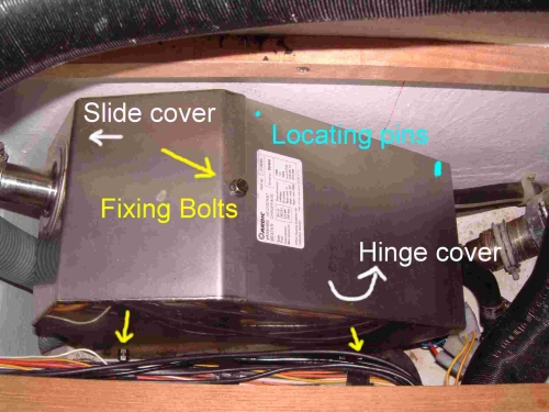
Remove the heater cover. Unscrew 3 bolts, push the front cover forward and hinge the cover upwards until the locating pins are released.
In the boat: Switch the heater on at the control-unit.
In the locker: Check the water pump for noise. Squeeze the water pipes to feel for flow. No noise from the pump probably means a faulty pump (subject to the next item re-set switch)
Identify the re-set switch grommet. Remove the grommet and try to reset the switch. It will click on reset. To reset the switch insert a flat bladed screwdriver into the hole (10mm) and push sideways to the right (the switch is mounted to the right of the hole.)
If the switch ‘clicks’ on the previous operation the water pump may not be faulty. You will be able to hear the pump running if it works and you will be able to feel the water flowing in the pipes if it is pumping water.
A replacement pump is easy to fit, it slides out of the rubber mounting collar after the pump pipes have been removed. Clamp the pipes to prevent water loss. The pump has been changed from a direct impeller drive to magnetic impeller drive to prevent the motor melting down if the impeller stalls. You may need to crimp bullet terminals on to the pump wires to fit into the pump-connector
Bleeding the system
The heater may be connected to the heating circuit on both sides of a one way valve (see note below). This allows water to bypass the heater under engine operation. I found that the air would be pumped out of the heater and sucked back round via the valve. To avoid this I found that running the engine helped to remove the air.
Bleeding is done via the small bleed knob/screw. I found that I had to remove the engine header tank lid, run the engine and turn the heater on to get the air out of in the heater. You can also help the process by filling the pump with water by removing the top outlet hose.
Caution: If the heater is run without water the over temperature reset-switch will trip. If there is air and water in the heater then steam will be produced and water will blow out of the engine-header tank. So restrict air-bleeding to the time before the heater fires up.
Note 1: Later systems fitted with the new pump with magnetically driven impeller do not have the one way valve and the pump is connected directly into the heating/cooling water circuit.
Note 2: Ardic is now owned by Eberspacher, see their web site for dealers and support. www.eberspacher.com
Problems with Heat Output
There have been complains about the hot air temperature of the heater. If the engine is cold it will sap heat from the hot water and hence the hot air, whilst if the engine is hot it will assist the temperature of the hot air. Solution run the engine for a short time to get it to temperature.
ANOTHER SOLUTION….(provided by www.eberspacher.com)
By carrying out a modification to the heater circuit which includes the installation of a thermostatic valve and a check valve, a considerable improvement can be made to the performance of the heating system. In effect, the engine block is taken out of the circuit when the water circuit temperature is below 75 degrees centigrade, once the temperature has exceeded 75 degrees the thermostatic valve will allow flow through the block until the temperature once again falls to below 75 degrees.
Air-locks
If the system has air in it the water will not flow. Symptoms of this are heater-cycling, no heat output and smoking exhaust. If the engine coolant is drained the system must be bled. There is an air-bleed screw under the cockpit locker near the heater unit. On older systems the water pump (mounted inside the Ardic heater-unit) has a direct drive and can seize if run dry. On newer units a pump with a magnetic-coupling is fitted to prevent this. The pumps can be identified:
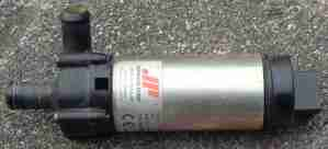 O
O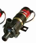 lder pump (left) – Johnson Pump Type CO30P6-1
Newer pump (right) – Johnson Pump Type CM30P7-1
The older pump has an impeller housing (the black bit on the left with the hose connections) of 28mm length, the new pump has a longer housing.
See the Johnson Pump website for info www.johnson-pump.com/JPMarine/default.htm